-

Electronic Team, Inc. • 2019-08-28T09:02:47
Submit your email address to get a link for quick download on your desktop and get started!
This article describes the RS485 pin configuration including diagrams of full and half duplex RS485 connector pinouts. It also covers the technical RS485 specifications
In the EIA’s standard series, the RS485 protocol is considered the most versatile, demonstrating good performance on all four criteria. This has led to the RS485’s wide adoption as the communication interface of choice when multiple nodes need to communicate in control or data acquisition applications.
Contents
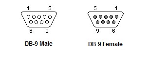
Figure 1. RS485 connector pinout
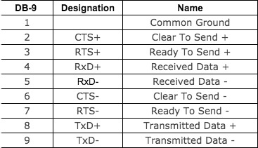
Figure 2. RS485 pinout
Carrier Detect (CD) this control signal is used when a modem informs a computer that it has detected a carrier that the computer can use for data transmission.
Receive Data (RXD) this line is used for data transmission between two sources. An example is data received from a modem transferred to a computer.
Transmit Data (TXD) this is the line that actually carries the transmitted data.
Data Terminal Ready (DTR) this is the signal that shows that a computer is ready for transmission.
System Ground (GND) refers to a physical connection with the ground, a baseline used for measuring voltages in an electrical circuit, or a shared path for returning electrical current.
Data Set Ready (DSR) in contrast to the DTR signal, this signal notifies a computer or terminal that the modem is operational and capable of receiving data.
Request to Send (RTS) positive voltage is necessary for this signal to allow the request to send (RTS) to be performed. It indicates that interference-free transmission is possible between the data set and the data terminal.
Clear to Send (CTS) sending this signal after a connection between a data terminal and a modem has been established confirms recognition by the data terminal that communications can commence.
Ring Indicator (RI) the purpose of this signal is to alert a modem operating a data set that a low frequency has been detected. The signal simply alerts the data terminal but does not impact the data transmission between the devices.
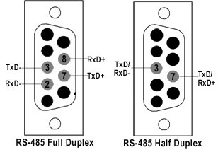
Figure 3. 9 pin RS485 pinout
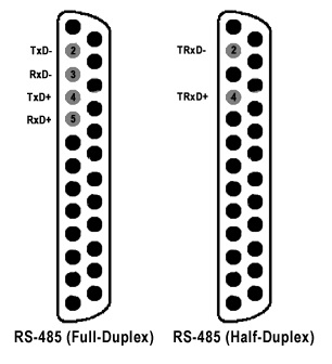
Figure 4. RS485 pin configuration for DB 25
Figure 3 is an RS485 wiring diagram for RS485 pinout DB9 connectors.
Figure 4 is a pin diagram for both 25 pin RS485 pinout half duplex and full duplex pinout connectors. The TxD+ and TxD- lines carry transmit data while the RxD+ and RxD- contain the receive data. The distances these signals are carried is greater due to differential signals.
The RS485 interface achieves superior transmission over greater distances and better data rate performance than the RS232 protocol. Transmission speeds of 30-35 Mbps are supported for distances of up to 10 meters. Data rates of 100Kbps can be achieved over distances of up to 1200 meters. RS485 is primarily used in multi-drop configurations that make use of its balanced differential interface. Figures 3 and 4 show an RS485 pinout diagrams for 9 pin DB9 and 25 pin DB25 connectors
As displayed in the RS485 cable pinout, the interface has all signals in differential configurations.
CTS+ and CTS- and the RTS+ and RTS- signals are all employed as handshake control signals.
TxD+ and TxD- perform data transmission.
RxD+ and RxD- are the lines that are used to collect data.
Multi-drop configurations enable up to 32 devices to be connected with a single controlling master device. An example is the VSAT NMS (Network Management System). In this implementation, software running on a PC monitors and controls a variety of subsystems. These include MUXs, modems, RF up and down converters, and other network components. In order for this type of implementation to work correctly, properly wired RS485 connectors are required on the PC running the NMS application as well as all of the connected subsystems.
The RS485 (EIA485) interface has proved to be extremely robust and is the most popular communication protocol used in industry due to its multi-point topology. The RS422 protocol has similarities with RS485 in that both conduct data transmission using differential signals.
There are two types of RS485:
Full-duplex mode is used when you need to be able to transmit and receive data at the same time. In half-duplex mode, you can only transmit or receive data at any given time.
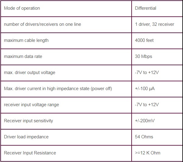
The voltage range on the lines varies from -7 V to +12 V.
There is no specific type of connector used to implement the RS485 protocol but in most scenarios, a DB9 connector or terminal block are employed.
Specific RS485 connectors may have different pinouts. You will be able to determine the actual configuration based on the documentation that accompanied the device.
Connect RS485 devices with 2 contacts.

Figure 5. RS485 pinout half duplex
Connect RS485 devices with 4 contacts.
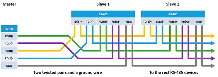
Figure 6. RS485 full duplex pinout
The RS485 employs a set of 120 Ohm termination resistors located at each end of the line. This is necessary to allow long-distance data transmission.
A description of the RS485 technical specifications is provided in the following table.
